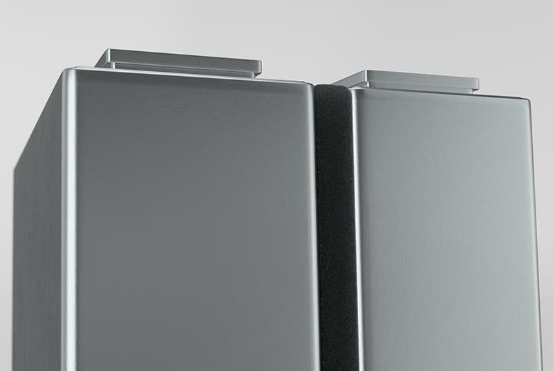
Uncontrolled battery-cell expansion can deform modules, loosen electrical connections, damage busbars, and eventually trigger costly battery-pack failures.
An EV battery cushion pad solves this problem by absorbing cell expansion while maintaining controlled and uniform pressure inside the battery module.
An EV battery cushion pad is an engineered compressible layer installed between pouch or prismatic battery cells. It is also called a battery compression pad, cell-to-cell pad, pressure-management pad, or tolerance pad.
Without a properly designed cushion pad, repeated cell swelling can create excessive local pressure, cell movement, connector stress, and premature module degradation.
The correct solution is a low-compression-set pad with a controlled compression force deflection curve matched to the battery cell’s pressure window.
The pad compresses when the cells expand and pushes back when they contract. This controlled response keeps the cell stack stable without applying damaging pressure to the cell casing.
Incorrect: An EV battery cushion pad is simply a piece of soft foam.
Correct: It is a pressure-management component engineered around cell swelling, operating temperature, compression set, dielectric strength, vibration, and assembly tolerances.
How Does a Battery Compression Pad Work?
A pad that becomes too hard can crush or overload cells, while a pad that is too soft may allow movement, vibration damage, and loss of module stability.
The effective solution is to select a material with a predictable stress-strain response and a stable pushback force across the required compression range.
Engineers evaluate this behavior through compression force deflection, or CFD. CFD shows how much force the pad applies at different compression levels.
A relatively flat and controlled CFD curve helps the pad accommodate cell expansion without producing a sudden pressure increase. Low compression set is equally important because the pad must recover rather than remain permanently flattened.
What Functions Can an EV Battery Cushion Pad Provide?
Using a single-purpose foam without checking the full module environment can leave the battery vulnerable to vibration, electrical leakage, assembly errors, and pressure imbalance.
A multifunctional automotive-grade cushion pad should be selected according to mechanical, electrical, thermal, and manufacturing requirements.
Depending on its material and construction, an EV battery cushion pad can provide the following functions:
Cell-expansion compensation: Accommodates reversible breathing and permanent swelling.
Pressure management: Maintains a controlled force across the cell stack.
Vibration reduction: Limits relative movement between adjacent cells.
Shock absorption: Reduces mechanical loads during road impacts and vehicle operation.
Tolerance compensation: Absorbs cell and module dimensional variation.
Electrical insulation: Helps separate conductive battery components when dielectric materials are specified.
Assembly support: Holds cells in position during automated module production.
Which Material Is Best for an EV Battery Cushion Pad?
Selecting material only by price or softness can result in permanent deformation, uncontrolled pressure, insulation failure, or rejection during battery validation.
The best material is the one whose compression, temperature, dielectric, aging, and flammability properties match the specific cell and module design.
Microcellular polyurethane and silicone foam are widely used, but they behave differently under heat, humidity, compression, and long-term aging. Specialized multilayer pads may also combine compressible foam with mica or another thermal-insulation layer.
Material or Construction
Main Advantage
Critical Limitation to Check
Typical Application
Microcellular polyurethane foam
Controlled compression and good dimensional efficiency
Temperature, humidity aging, and compression set
Pouch and prismatic cell pressure management
Silicone foam
Good temperature stability and resilient cushioning
Cost, stiffness, thickness, and gas-release requirements
High-temperature or flame-resistant module areas
Foam with adhesive surface
Faster positioning during automated assembly
Adhesive aging, liner removal, and reworkability
High-volume module production
Foam with mica barrier
Combines compression with improved thermal insulation
Thickness, edge sealing, weight, and thermal validation
Cell-to-cell thermal propagation control
Standard industrial foam
Low initial material cost
Unverified pressure retention, dielectric performance, and aging
Not recommended without full validation
Where Is an EV Battery Cushion Pad Installed?
Placing the pad in the wrong location can create uneven compression, interfere with cooling paths, damage sensors, or transfer force into busbars and high-voltage connectors.
The pad should be positioned according to the cell expansion direction, module restraint system, electrical layout, and thermal-management design.
The most common location is between adjacent pouch or prismatic cells. Pads may also be placed between an end cell and the module end plate or at selected module interfaces.
The pad must not obstruct venting channels, cooling surfaces, pressure sensors, thermistors, busbars, or wire-harness routing. Its die-cut shape should follow the functional cell area rather than simply copying the cell outline.
Which Tests and Standards Should Be Considered?
A pad that performs well in a room-temperature compression test may still fail after thermal aging, humidity exposure, vibration, or thousands of charge cycles.
Validate the pad at material, cell-stack, module, and complete battery-pack levels under the intended automotive environment.
Important material tests include CFD, compression set, stress relaxation, dielectric strength, flammability, temperature aging, humidity aging, and chemical compatibility.
Battery-level requirements may reference standards such as ISO 6469-1, UL 2580, SAE J2380, SAE J2929, and UNECE Regulation No. 100. These standards apply mainly to battery systems and vehicle safety; they do not automatically certify an individual cushion pad.
Frequently Asked Questions
Unclear terminology often causes buyers to request the wrong foam, thickness, or safety function.
Use the following direct answers to define the application before requesting a quotation or sample.
How thick should an EV battery cushion pad be?
An arbitrary thickness can over-compress the cell or leave the module loose. Pad thickness must be calculated from available space, preload, cell tolerance, expected swelling, and allowable pressure.
Does a cushion pad prevent thermal runaway?
A standard cushion pad may burn or transfer heat to adjacent cells during a severe thermal event. Use a specifically tested thermal-propagation pad when thermal runaway mitigation is required.
Is polyurethane or silicone better for battery pads?
Choosing by material name alone can produce the wrong temperature or pressure response. Polyurethane is often selected for efficient pressure management, while silicone may offer stronger high-temperature performance; final selection requires application testing.
Final Engineering Recommendation
Treating the EV battery cushion pad as an inexpensive foam insert can turn a minor material decision into cell damage, intermittent high-voltage faults, warranty claims, and complete module revalidation.
Treat it as a precision pressure-management component and validate it together with the cells, end plates, cooling system, busbars, connectors, and high-voltage wire harness.
From my 15 years of automotive wire-harness and high-voltage interconnection experience, I have learned that mechanical pressure inside a battery module never affects only the cells. It eventually reaches terminals, busbars, connectors, sensors, and harness routing points.
My practical rule is simple: control cell movement before it becomes an electrical connection problem. Before approving any EV battery cushion pad, verify the pressure curve, compression set, dielectric performance, environmental aging, and end-of-life cell expansion with actual module data.
We use cookies to enable all functionalities for best performance during your visit and to improve our services by giving us some insight into how the website is being used. Continued use of our website without having changed your browser settings confirms your acceptance of these cookies. For details please see our privacy policy.